
Investigating the Swissair Flight 111 In-flight Fire using the SMARTFIRE CFD fire simulation software.
AT 8.18pm on 2 September 1998, Swissair Flight 111 (SR 111), took off from New York’s JFK airport bound for Geneva, Switzerland. Tragically, the MD-11 aircraft never arrived. According to the crash investigation report, published on 27 March 2003, electrical arcing in the ceiling void cabling was the most likely cause of the fire that brought down the aircraft. No one on board was aware of the disaster unfolding in the ceiling of the aircraft and, when a strange odour entered the cockpit, the pilots thought it was a problem with the air-conditioning system. Twenty minutes later, Swissair Flight 111 plunged into the Atlantic Ocean five nautical miles southwest of Peggy’s Cove, Nova Scotia, with the loss of all 229 lives on board.
A full account of the investigation into Swiss Air Flight 111 can be found at http://www.pbs.org/wgbh/nova/aircrash/
Reconstruction of the wreckage disclosed that the fire pattern was extensive and complex in nature. The fire damage created significant challenges to identify the origin of the fire and to appropriately explain the heat damage observed. The SMARTFIRE CFD software was used to predict the “possible” behaviour of airflow as well as the spread of fire and smoke within SR 111. The main aims of the CFD analysis were to develop a better understanding of the possible effects, or lack thereof, of numerous variables relating to the in-flight fire. Possible fire and smoke spread scenarios were studied to see what the associated outcomes would be. This assisted investigators at Transportation Safety Board (TSB) of Canada, Fire & Explosion Group in assessing fire dynamics for cause and origin determination.
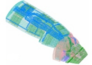
The fire simulations in this study were performed using a special version of the SMARTFIRE V3.0 software with features developed particularly for this project. The SMARTFIRE CFD model was constructed from a simplified version of a detailed, 3D CAD aircraft model provided by the TSB. Due to the highly complex nature of the geometry in the aircraft, some of “small” features and components had to be either approximated or removed from the geometry to make the SMARTFIRE computer files manageable. A further simplification of some of larger components was also necessary due to the complex nature of some of the shapes involved. In any case, the changes made in the geometry were discussed with the TSB to ensure that those modifications would be of little consequence to the airflow and fire. The unstructured computational mesh consisted typically in excess of 280000 tetrahedral elements.
 |
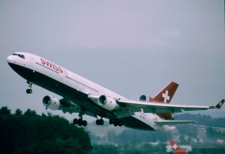 |
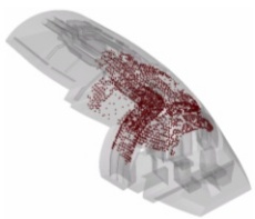
FIGURE 1: The SMARTFIRE mesh and the MD11 aircraft.
The pre-fire airflow CFD analysis was performed first. The initial and boundary airflow conditions at the various flow components in the CFD model were provided by the TSB (e.g., conditioned air supply rates into and out of the cockpit). The model was then run and the velocity vectors and flow rates were studied at different locations within the virtual aircraft. Some adjustments were made to those boundary flow rates until the airflow patterns in the computer model closely matched those observed in actual aircraft during airflow flight tests.
The fire initiation site, as provided by TSB, was prescribed with the aid of a volumetric heat source. The source was adjusted so as to sustain the combustion of the materials over a short duration to allow flame propagation. Criteria for the fire propagation are: 1) critical radiative heat flux from the surrounding fire that would ignite nearby material; 2) critical surface ignition temperature; 3) a combustible surface cell is allowed to ignite if it is in the vicinity of a region of a flame tip for two seconds or more; 4) the surface cell is also allowed to ignite based on experimental flame spread data for similar thin-films considered here.
Six fire simulations were carried out in transient mode. The initial flow conditions for these fire simulations were obtained from the pre-fire simulations performed as part of the fire simulation. These cases consisted of various modifications leading to the final scenario of interest. Only the final simulation results with all the required revisions implemented are reported here.
 |
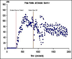 |
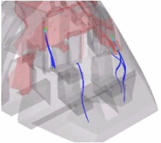
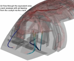
| Figure 1: Flow rate at cockpit ceiling crack. | Figure 2: Flow rates at the smoke barrier. |
 |
 |
| (a) at 850 seconds | (b) at 1500 seconds |
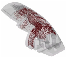
Figure 3: Fire spread at (a) 850s and (b) 1500s
Shown in Figure 1 are low smoke concentration surface maps during the early stages of the fire. It depicts the onset of small traces of smoke entering the cockpit at (i) the crack adjacent to the Avionics CB Panel, close to the right overhead diffuser, and (ii) through the small opening in the cockpit ceiling liner located above and to the left of the Captain’s seat. Figure 2 depicts the flow rates vs. time at the smoke barrier. In this simulation, at approximately 5 minutes after the fire started, part of the smoke barrier collapsed due to high temperatures. The positive value indicates that air was being drawn aft, out of the cockpit through the newly created opening. Figure 3 shows the fire damage on the insulation blankets and the riser ducts at 850 seconds just after the Cabin Bus was switched OFF. The predicted damage both aft and forward of the cockpit wall was 3.8 and 1.4 metres respectively at 850 seconds and 5.6 and 1.6 metres at 1500 seconds respectively. This compares well with data available from the SR 111 investigation, where extensive fire damage in the area above the ceiling in the front section of the aircraft was concentrated about 1.5 metres forward and 5 metres aft of the cockpit wall.
SMARTFIRE animation of fire development.
Real
Media (low quality) - streamed from the server [34 sec]
Real
Media (good quality) - downloadable [1.87 MB]
With the successful completion of this project, SMARTFIRE has become the first fire model to be used in an air crash investigation. The official TSB report acknowledged the technology’s successful debut in ‘helping to develop better insight into and understanding of the fire’. This study has demonstrated that CFD based fire analysis is a cost effective approach to investigating complex flow/fire scenarios and that coupled with well targeted controlled experiments generating quality experimental data, CFD fire simulation can be a powerful tool in aircraft accident investigation. This study represents a significant milestone in the use of Computational Fire Engineering (CFE) tools, such as SMARTFIRE in forensic analysis.
Reference:
"Flight Simulation". Jia F., Patel, M. and Galea E.R. Fire Prevention Fire Engineers Journal, October 2003, pp27-29, 2003.
See publications #162, 95, 83, 71, 64-62, 30, 29, 27, 25, 22, 19, 17, 16, 10.
![]()
![]()