
| smartfire |
Home |
Capabilities |
Features |
Background |
Future |
Projects |
Publications |
Animations |
News | Press Releases | Leaflets | Team | Visitor Registration | Demo Software | Users Area | Contact |
|
|
BACKGROUND
SMARTFIRE: A Fire Field Modelling System for the Simulation of Fires in the Built Environment
Aims
of the SMARTFIRE development Back
A key aim of the SMARTFIRE development is to make Fire Field Modelling techniques accessible to non-Computational Fluid Dynamics (CFD) experts; such as fire fighters, architects or safety engineers. In addition, SMARTFIRE is intended to be a useful tool for the researcher and expert consultant in fire safety engineering. To achieve these aims SMARTFIRE has been based on an open architecture with a powerful Case Specification Environment, an automated meshing system and an interactive CFD Engine.
By embedding expert knowledge into the CFD software and the meshing system, SMARTFIRE removes much of the black-art associated with CFD analysis. Critical tasks such as the selection of solvers, relaxation parameters, convergence criteria, time steps, meshing and boundary condition specification are all supported by automated tools and expertise within the SMARTFIRE system. The user is given the option of overriding these decisions, thus retaining ultimate control. In this way, the safety professional need simply specify a scenario in terms of known geometry and fire characteristics, using familiar terms of reference, and the SMARTFIRE system will use embedded expertise to configure the simulation.
The development and integration approach taken in SMARTFIRE is to use an open architecture blackboard structure. This architecture allows flexible and reliable communication of status and control information between all of the constituent software modules.Our ongoing research aims to deliver inter-cooperating processes and coupling that will give enhanced levels of performance, stability and realism.
The CFD Engine within SMARTFIRE has been designed with the above points in mind, using object oriented techniques and has been implemented in C++. The CFD numerical component is capable of solving three-dimensional, turbulent, buoyant, radiant and compressible flows on both structured and unstructured meshes, with an option of solving for simple gaseous combustion and smoke. Unlike conventional CFD technology this allows extremely complex geometries to be efficiently meshed, allows localised mesh refinement and potentially provides the ability to remove cells from blocked or remote regions - thus saving large amounts of wasted CPU time. The delivery of advanced unstructured meshing techniques are currently in an advanced stage of research and development and are intended to be made available in near future releases.
The embedded expert knowledge in SMARTFIRE currently concerns problem set up (static knowledge). The problem set up support takes a simple physical description of the simulation scenario and converts it into an optimal model configuration.
A key aspect of
the CFD engine is its novel use of unstructured group
solvers, whereby similarly related cells can be
collected together to form logical groups. Once grouped,
all cells in a group can have a group-based solution
control. The whole problem domain will generally be
comprised of a number of such groups. Thus the overall
solution strategy can be optimised using local group
controls to target more processing or specific control
configuration where it is most needed. This concept has
been further enhanced with research to provide a hybrid
field / zone capability. This will use the low
computational expense of zone modelling in regions where
it is acceptable to do so, with consequent performance
gains.
SMARTFIRE also benefits from a parallel implementation (using networked PCs in a computational cluster and/or multiple cores within a single Workstation) to speed-up the simulation process and allow very large cell budget cases to be simulated. There are now both 32 bit and 64 bit executables for most of the components of the SMARTFIRE environment. The 32 bit executables will be limited to the 2 GB memory addressing limit imposed by 32 bit Windows, however the 64 bit executables will be able to run much larger scenarios up to the free memory available. The use of parallel architectures allows the user to sidestep perfomance issues of using only one CPU, by handling only a portion of the entire job on each processing node (or core) in the computational cluster. Parallel SMARTFIRE does require certain capabilities (e.g. MPI communications protocol and a fast network, preferably with low latencies) and launching the software is slightly more complex due to having to configure and select all of the PCs that will participate in the parallel simulation. Parallel SMARTFIRE has a dedicated launcher specifically aimed at facilitating the launch process and the Parallel SMARTFIRE User Interface has been developed to be as familiar as possible to existing SMARTFIRE users.
SMARTFIRE v4.2 incorporates the latest prototype parallel implementation of the SMARTFIRE Interactive CFD Engine. Parallel Processing has been used for many years in the field of computational modelling. Parallel processing distributes the computational task over a number of processors and therefore allows computational problems to be solved in a shorter timeframe, essentially by utilising more computational power. The majority of this work has focussed on the use of specialised hardware such as large scale UNIX based multiprocessor systems. The majority of engineering firms that would benefit from the reduced timeframes offered by parallel processing rarely have access to such specialised systems. However, in recent years with the increasing power of individual office PCs / desktop workstations and the improved performance of Local Area Networks (LANs) it has now come to the point where parallel processing can be usefully utilised in a typical office environment. A dynamic load balancing scheme has also been devised, for future release, to allow the effective use of the software on heterogeneous (dissimilar processing capabilities of the processing nodes) PC networks. The parallel implementation of SMARTFIRE makes use of standard networked office PC's and/or multiple (real) cores in a single PC.
|
EXAMPLE 1a: Geometry of multi-room structure to be modelled in SMARTFIRE |
EXAMPLE 1b: View from SMARTFIRE fire simulation, colours represent temperature. Plane parallel to floor and 2m above floor depicted. Fire originates in corridor. |


|
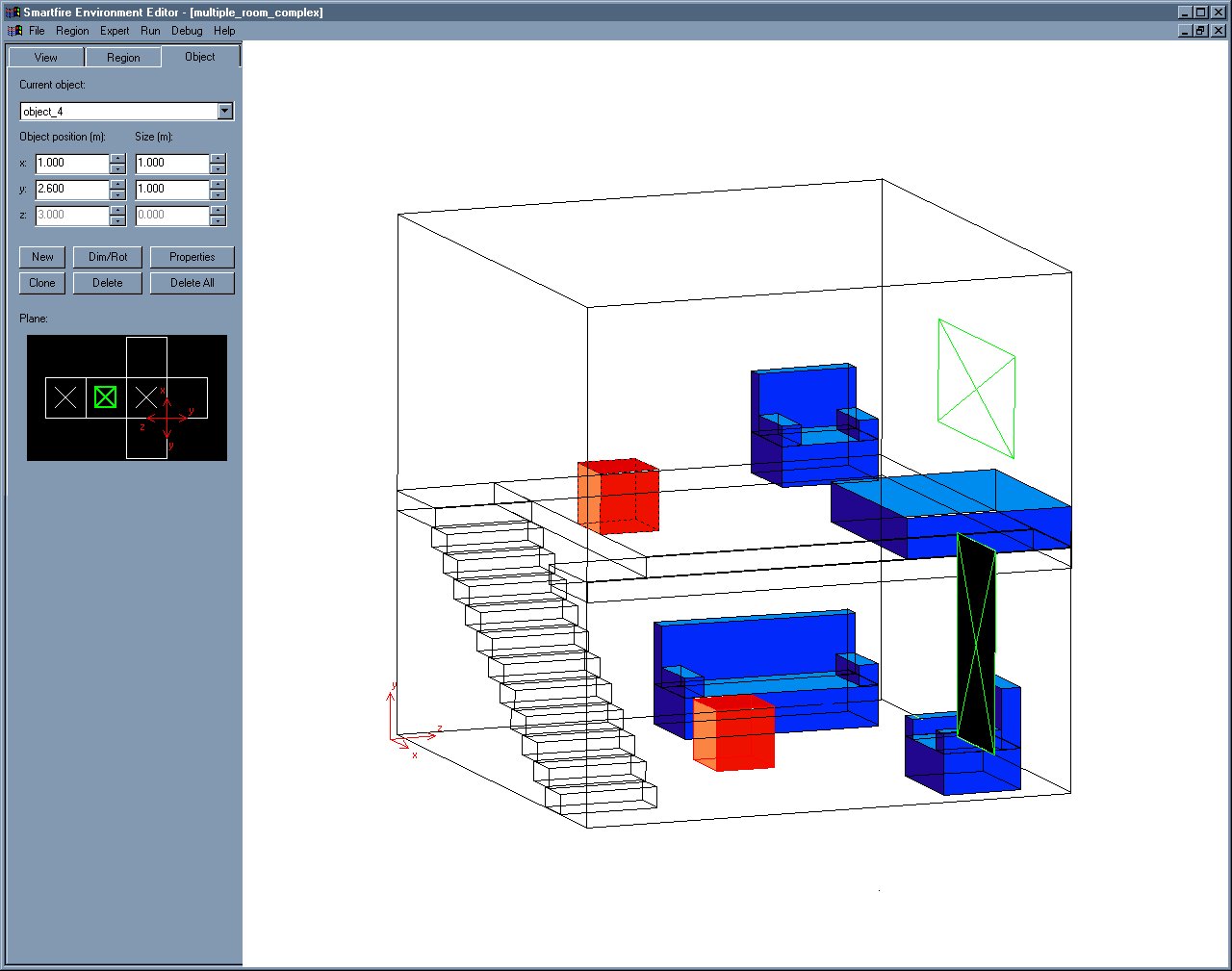
EXAMPLE 2a: Geometry of multi-floor structure to be modelled in SMARTFIRE
|
EXAMPLE 2b: View of SMARTFIRE generated mesh for multi-floor structure
|
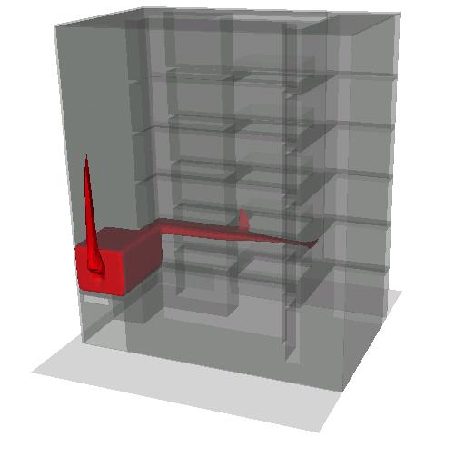
EXAMPLE 2c: View from SMARTFIRE fire simulation, colours represent temperature. Vertical centre plane is depicted passing through both floors. Note fire source on second floor was ignited by conditions generated by first fire source. |

|
EXAMPLE 3: Fire in a six storey building simulated using SMARTFIRE. The fire starts in a room on the first floor and the hot gases can be seen to be spreading on the first floor and up the central atrium. The hot smoke is also emerging from the window of the room containing the fire. This geometry was created using the standard SMARTFIRE meshing tools. Visualised using MayaVi. A VRML version of the visualisation can be viewed here. A VRML viewer plug-in can be downloaded here. |
|
EXAMPLE 4: SMARTFIRE is used to identify the spread of CO from two differing cable types when set on fire in identical conditions. It is clear that the cable used in lower picture produces far less CO than the cable used in the upper picture. Visualised using MayaVi. |
|
EXAMPLE 5: SMARTFIRE is used here to simulate a fire starting is a ships cabin. Hot combustion gases are seen spreading down the ships corridor after the door of the cabin, containing the fire, fails. |


Overview of
the SMARTFIRE Software Components Back
SMARTFIRE is
an open architecture CFD Environment with an integrated
knowledge based system that attempts to make Fire Field
Modelling accessible to non-experts in CFD. There
are five major components to the software: The
pre-processing User Interfaces, an Interactive Meshing
System, the Interactive CFD Engine and a Post Processing
Visualization System. By embedding expert knowledge into
various components (including the CFD Engine), fire
field modelling is made more accessible to fire
engineers who have limited CFD expertise. The
expertise currently embedded within the code is also
used to support the critical task of mesh specification
of fire field simulation scenarios. Ongoing research
will soon deliver an Intelligent Control System and
Experiment Engine to provide automated dynamic control
of the solution process.
The software developed at
the University of Greenwich uses a combination of
in-house and proprietary software building blocks and is
designed to run on PC's under most current 32 bit or 64
bit Windows Operating Systems.
The SMARTFIRE Scenario Designer
The Scenario Designer provides support for designing a fire modelling scenario from scaled 2D floor plans (from DXF file format or mono bitmap image). The tool has an interactive CAD-like interface that allows a multi-storey building to be built up from the addition of floor plan storeys. The system has semi-automated room and door searching capabilities that attempt to identify walls (to determine room blocks) and doors. Even if no suitable floor plans are available, the tool still provides a powerful interface for the manual entry of buildings using 2D floor plan design.
Once a complete building has been specified, the Scenario Designer will create a SMARTFIRE model that can then be configured for simulation in the SMARTFIRE Case Specification Environment.
The SMARTFIRE Case Specification Environment
The Case Specification Environment is a dedicated Graphical User Interface (GUI) used to specify the problem. Through this GUI, the user sets the geometry, i.e. location of walls, wall materials, internal compartments, obstacles, location of vents, fires, inlets, outlets, monitors and any other required objects. The GUI also provides control of all of the physical models (e.g. Radiation, Combustion, Smoke) and the nature of the simulations (e.g. material usage, simulated time duration, time stepping and ambient conditions). The Case Specification Environment also incorporates the Automated and Manual meshing system. This tool generates the command script and mesh files that are used to start the simulation in the CFD engine. All of the terminology used in the GUI is designed to be as familiar as possible to the User so, for example, the material type is specified using terms such as ‘brick’, ‘insulator’, etc, and the conversion to numerical material properties and specific boundary conditions is performed internally. Fires are specified either as a volumetric heat source or using a gaseous combustion model with a fuel release rate. Multiple fire sources and multi-stage fires can be modelled. SMARTFIRE also possesses thermal radiation transfer models using radiosity, six-flux as well as a multi-ray radiation model.
The SMARTFIRE Interactive Meshing System
SMARTFIRE possesses an automated grid generation component. This generates the CFD mesh of control volume cells for the problem using the Knowledge Base System (KBS) rules to determine an appropriate cell budget and an initial mesh. The system is capable of meshing multi-compartment enclosures. It uses rule based technology to produce a reasonable grid based on the geometrical and scenario data input by the user. Once the user has specified the geometry, scenario and cell budget, the automatic mesh generation system begins operation. First, the cell budget is checked. Expert rules are used to suggest an approximate minimum realistic cell budget from the user-defined input. These expert rules are based on experience and take into consideration overall geometry dimensions, aspect ratios, wall refinement etc. Next, the geometry is checked. If two objects are too close to each other in a particular coordinate direction, this will be reflected in the mesh as a slice of very thin cells in that particular direction. Expert rules check aspect ratios and edge lengths between neighbouring cells to ensure that these are not excessive. The meshing system assesses the contents of each slice in the geometry and determines an appropriate local meshing strategy. Once all slices have been visited, the system adjusts the cell distribution to match the user specified cell budget. The meshing system is aware of the power law requirements for turbulence handling (obeying the y+ boundary layer distance). For slices not at the edges of the domain, other rules are used. These attempt to resolve extreme edge length ratios of cells across slice boundaries. The expert user also has complete control over the meshing within the slices through the mesh editing tool. This tool is graphical selection (point and click) based making the tailoring of problem specific meshing features quite straight forward. The KBS also monitors key inputs to check for inappropriate settings or recommended actions.
The SMARTFIRE CFD Engine
The CFD Engine, written in C++, uses validated numerical methods enhanced by object-oriented developments. Internally, it uses three-dimensional unstructured meshes, enabling complex, irregular geometries to be meshed. Unlike many conventional general- and specific- application based CFD software packages, this allows complex multi-compartment geometries to be meshed efficiently and automatically. Additional physics features included, for Fire Field Modelling, include various thermal radiation models, provision for heat transfer through walls, simple gaseous combustion models, smoke modelling, provision of fans and forced ventilation flows, ceiling mounted natural vents and the important buoyancy modification to the turbulence equations. Recent additions include the modelling of toxicity (CO and CO2), HCl release (with optional wall absorption modelling) and HCN. The CFD code also features optimised solvers, visual and graph interactive solution monitoring and Expert settings control interfaces.
The CFD code has its own unique windows based user interface. Unlike many traditional fire field models, this allows the user to interact with the solution through observation of the developing solution and by allowing the user to make adjustments to control parameters while the code is in operation. Adjustment such as this, in traditional CFD codes, typically involves stopping the simulation, saving restart files, editing input files, and finally restarting the simulation. With SMARTFIRE, this form of dynamic user control is considerably easier. All that is required is to point and click buttons and set appropriate values on the user interface.
The SMARTFIRE Data View Post Processing Visualization System:
The SMARTFIRE environment provides a simple, yet effective, interface for the post-processing visualization of data generated from the SMARTFIRE CFD Engine. Currently supported are iso-surfaces, multiple scalar or vector cut-planes, velocity vectors, streamlines, volumetric smoke visualization and semi-transparent geometry display. The tool also provides very easy-to-use animation creation facilities for the creation of a movie of a set of results data files.
|
EXAMPLE 6a: Geometry of multi-floor structure with domed roof to be modelled in SMARTFIRE. This makes use of the unstructured nature of the SMARTFIRE software (currently under development).
|
EXAMPLE 6b: View from SMARTFIRE fire simulation, colours represent temperature. Vertical centre plane is depicted passing through both floors. Note that the fire source on the second floor was ignited by conditions generated by first fire. Case uses an unstructured mesh (under development). |


|

SMARTFIRE
Architecture Back

|
SMARTFIRE
Validation Back
A number of validation
exercises have been undertaken with SMARTFIRE.
An extensive CFD validation document - which is provided
with the software - has been developed, that covers both
the basic physics of the CFD and the fire modelling
functionality. The basis of this work has been
extended to cover a general methodology for the
validation of fire models that is being supported by the
UK
Home Office. In addition, the mesh
generation capabilities have been tested, in a
systematic manner, both in-house on research projects
and by users in the field.